
98 Cherokee ODBII/CCD Bus Voltage Fails Check
 03-08-2014, 09:23 AM
#1
Newbie
Thread Starter
Join Date: Feb 2014
Location: HSV, AL
Posts: 28
Likes: 0
Received 0 Likes
on
0 Posts
Year: 1998
Model: Cherokee
Engine: 4.0
98 Cherokee Sport, 4.0 Engine, Auto Trans, 4x4
Background: recent purchase, no CEL displayed.
I tried this Key Trick procedure: Newer (OBDII) models - Put the key into the ignition, push down the odometer reset button, then turn the key to RUN with your finger on the button - and then release the button. The odometer will go through 1111111 through 999999, then display the car's serial number. On mine, once the 999999 is displayed, display returns to odometer reading, no codes shown. I discovered I don’t see the “check engine” light on the gauge cluster, so gonna check the bulb.
I have a “CarChip” ODBII reader, but it wouldn’t read any codes either. I had the ODBII scanned at AutoZone and they were successful and downloaded four CELs, an O2 sensor (didn’t get the #, but my rear of cat O2 is disconnected, cat removed by PO and these: P0700/P0705/P0743.
Researching ODBII troubleshooting here, I found CCKen’s thread on testing the Data Link Connector (aka ODBII connector):
https://www.cherokeeforum.com/f2/dlc...08/#post202988
excerpt from 2nd link:
“Pin 3, CCD Bus (+) and pin 11, CCD Bus (-) are fed from the PCM. If you put your voltmeter positive lead to pin 3 and your negative lead to a good ground near the data link connector you should read around 2.4 - 2.5 volts, and reading from pin 11 to a good ground you should read the same as at pin 3. You may see a slight variation.”
I get a good 12V on the pin 16>>ground and pin 16>>pin 4 checks. But on this Chrysler Crash Detection (CCD) voltage check, I got only 0.04 to 0.09V on both tests. There’s a note on the bus diagram that states: “If CCD Bus voltage is above 2.8V or below 1.8V communication on the CCD Data Bus stops or is invalid.”
I have removed and cleaned grounds G100, G101, and G102. All electrical systems are working, headlights, brakes, blinkers, windows, locks, horn… Airbag light comes on and goes off normally on initial start-up.
Where to look now to see what issues I have relating to the CCD voltage?
Last edited by RoyL; 03-08-2014 at 09:25 AM. Reason: typo
 03-08-2014, 10:06 AM
#2
CF Veteran
Join Date: Aug 2010
Location: Canton, MI
Posts: 8,357
Likes: 0
Received 90 Likes
on
74 Posts
Year: 1999
Model: Cherokee
Engine: 4.0
98 Cherokee Sport, 4.0 Engine, Auto Trans, 4x4
Background: recent purchase, no CEL displayed.
I tried this Key Trick procedure: Newer (OBDII) models - Put the key into the ignition, push down the odometer reset button, then turn the key to RUN with your finger on the button - and then release the button. The odometer will go through 1111111 through 999999, then display the car's serial number. On mine, once the 999999 is displayed, display returns to odometer reading, no codes shown. I discovered I don�t see the �check engine� light on the gauge cluster, so gonna check the bulb.
I have a �CarChip� ODBII reader, but it wouldn�t read any codes either. I had the ODBII scanned at AutoZone and they were successful and downloaded four CELs, an O2 sensor (didn�t get the #, but my rear of cat O2 is disconnected, cat removed by PO and these: P0700/P0705/P0743.
Researching ODBII troubleshooting here, I found CCKen�s thread on testing the Data Link Connector (aka ODBII connector):
https://www.cherokeeforum.com/f2/dlc...08/#post202988
excerpt from 2nd link:
�Pin 3, CCD Bus (+) and pin 11, CCD Bus (-) are fed from the PCM. If you put your voltmeter positive lead to pin 3 and your negative lead to a good ground near the data link connector you should read around 2.4 - 2.5 volts, and reading from pin 11 to a good ground you should read the same as at pin 3. You may see a slight variation.�
I get a good 12V on the pin 16>>ground and pin 16>>pin 4 checks. But on this Chrysler Crash Detection (CCD) voltage check, I got only 0.04 to 0.09V on both tests. There�s a note on the bus diagram that states: �If CCD Bus voltage is above 2.8V or below 1.8V communication on the CCD Data Bus stops or is invalid.�
I have removed and cleaned grounds G100, G101, and G102. All electrical systems are working, headlights, brakes, blinkers, windows, locks, horn� Airbag light comes on and goes off normally on initial start-up.
Where to look now to see what issues I have relating to the CCD voltage?
With key to RUN,
Read from DLC pin cacvity 3 to cav 4 or 5. You shuld see 2.49 volts.
Read from DLC pin cavity 11 to cv 4 or 5. You should see 2.51 volts.
Voltages may be slightly higher or lower, but not lower than 1.8 or above 2.8 volts (which are extremes).
Voltages may be close together as opposed to the normal .02 differential.
If you do get some real off the wall readings (like you stated above), disconnect the Transmission Control Module and try it again. If the CCD Bus (+) and (-) voltages come to where they should be, the TCM may be defective and corrupting the CCD Bus. See that DLC Data Link Pinout Schematic from my other post to see whch modules are connected to the CCD Bus.
If the TCM is bad, it may be causing your transmission DTC's that you mentioned in a different post.
Note that if you try to read CCD Bus voltages at the DLC with the ignition switch off you will see low voltages similar to what you said you got. These are the PCM idle/Differential voltages. Normally between .02 and .150 volts.
03-08-2014, 10:12 AM
#3
CF Veteran
Join Date: Aug 2010
Location: Canton, MI
Posts: 8,357
Likes: 0
Received 90 Likes
on
74 Posts
Year: 1999
Model: Cherokee
Engine: 4.0
98 Cherokee Sport, 4.0 Engine, Auto Trans, 4x4
Background: recent purchase, no CEL displayed.
I tried this Key Trick procedure: Newer (OBDII) models - Put the key into the ignition, push down the odometer reset button, then turn the key to RUN with your finger on the button - and then release the button. The odometer will go through 1111111 through 999999, then display the car's serial number. On mine, once the 999999 is displayed, display returns to odometer reading, no codes shown. I discovered I don�t see the �check engine� light on the gauge cluster, so gonna check the bulb.
You won't see any codes displayed on your '98 XJ when doing the Instrument Cluster Actuator Test. The key trick only works on '97 and below OBD XJ's.
03-09-2014, 09:35 PM
#4
Newbie
Thread Starter
Join Date: Feb 2014
Location: HSV, AL
Posts: 28
Likes: 0
Received 0 Likes
on
0 Posts
Year: 1998
Model: Cherokee
Engine: 4.0
You must have the ignition swith to RUN when checking the CCD Bus (+) and (-) circuits.
With key to RUN,
Read from DLC pin cacvity 3 to cav 4 or 5. You shuld see 2.49 volts. [still 0.04V]
Read from DLC pin cavity 11 to cv 4 or 5. You should see 2.51 volts. [still 0.04V]
Voltages may be slightly higher or lower, but not lower than 1.8 or above 2.8 volts (which are extremes).
Voltages may be close together as opposed to the normal .02 differential.
If you do get some real off the wall readings (like you stated above), disconnect the Transmission Control Module and try it again. If the CCD Bus (+) and (-) voltages come to where they should be, the TCM may be defective and corrupting the CCD Bus. See that DLC Data Link Pinout Schematic from my other post to see whch modules are connected to the CCD Bus.
If the TCM is bad, it may be causing your transmission DTC's that you mentioned in a different post.
Note that if you try to read CCD Bus voltages at the DLC with the ignition switch off you will see low voltages similar to what you said you got. These are the PCM idle/Differential voltages. Normally between .02 and .150 volts [reads 0.00V]
Plugged TCM back, checked, same > 0.04V
with key off, I get no voltage.
btw, same meter reads 12.0V on cav 16 to cav 4/5 grds. Gonna study the CCD wiring diagram some more before I go any further.
Thx, Roy
03-10-2014, 11:51 AM
#5
CF Veteran
Join Date: Aug 2010
Location: Canton, MI
Posts: 8,357
Likes: 0
Received 90 Likes
on
74 Posts
Year: 1999
Model: Cherokee
Engine: 4.0
Thx, Ken. I did check CCD voltage [cav 11 to cav4/5 and cav 3 to cav 4/5] with key in run position, reads 0.04V. disconnected TCM as suggested, and checked again... same, 0.04V.
Plugged TCM back, checked, same > 0.04V
with key off, I get no voltage.
btw, same meter reads 12.0V on cav 16 to cav 4/5 grds. Gonna study the CCD wiring diagram some more before I go any further.
Thx, Roy
Plugged TCM back, checked, same > 0.04V
with key off, I get no voltage.
btw, same meter reads 12.0V on cav 16 to cav 4/5 grds. Gonna study the CCD wiring diagram some more before I go any further.
Thx, Roy
Does everything else in your Jeep work? Instruments, RKE, Starts and runs okay? Which modules don't you have, as shown in the CCD Bus schematic?
I guess I can't blame your meter because it's reading 12 volts at 16, and the grounds (cavs 4/5) at G102 are okay or you wouldn't see 12 volts.
Unless you have an Autoranging voltmeter and its going nuts trying to read low voltages.
~~~~~~~
Try this:
Disconnect and isolate the battery negatve post connector.
Using an Ohmmeter, read resistance between DLC pin cavs 3 and 11. 60 Oms or 120 Ohms?
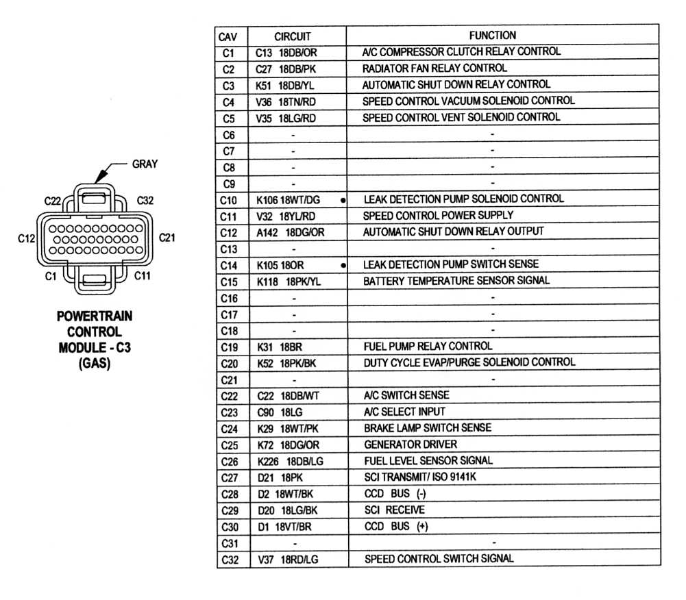
Next, Disconnect PCM connector C3 (Gray), and read between pin cavs C28 and C30. 60 Ohms or 120 Ohms? C3 pinout below.
Next, reconnect battery negative post connector.
PCM C3 still disconnected.
Read voltages at the DLC 3/11 to 4/5 again (key to RUN) and see what you get.
 03-15-2014, 10:46 AM
#6
Newbie
Thread Starter
Join Date: Feb 2014
Location: HSV, AL
Posts: 28
Likes: 0
Received 0 Likes
on
0 Posts
Year: 1998
Model: Cherokee
Engine: 4.0
Those readings are way off base.
Does everything else in your Jeep work? Instruments, RKE, Starts and runs okay? Which modules don't you have, as shown in the CCD Bus schematic? Everything is working, all lights, turn signals, power windows/locks, gauges all working. Fires up right away and idles fairly smooth, plugs look normal-grayish color, shifts thru all the gears and drives down the road at 70 MPH, has a little vibration at speed and has some engine noises I haven't identified yet...but overall seems good. I don't have overhead console or SKIM.
The only CEL I'm getting now is the rear of cat O2, which is disconnected.
I guess I can't blame your meter because it's reading 12 volts at 16, and the grounds (cavs 4/5) at G102 are okay or you wouldn't see 12 volts. Unless you have an Autoranging voltmeter and its going nuts trying to read low voltages.
I checked with two diff meters, readings are consistent. Changed scales on one meter to 1.5V, and got 0.05 vs 0.04V
~~~~~~~
Try this:
Disconnect and isolate the battery negatve post connector.
Using an Ohmmeter, read resistance between DLC pin cavs 3 and 11. 60 Oms or 120 Ohms? 60 ohms
Next, Disconnect PCM connector C3 (Gray), and read between pin cavs C28 and C30. 60 Ohms or 120 Ohms? 120 ohms
Next, reconnect battery negative post connector. PCM C3 still disconnected.
Read voltages at the DLC 3/11 to 4/5 again (key to RUN) and see what you get. Same, 0.04V. Same readings on 4 and 5.
Thx for the guidance. Finally got some time run these checks. See readings above in blue. btw, I checked the voltages again after putting everything back together, same - 0.04V.
Is the good news I don't have a bad PCM and the bad news I still have to keep chasing wires?
For what it's worth, likely related to the problem >> the "Carchip" OBDII gizmo I have is supposed to record various sensor data as you drive; bat voltage, speed, rpm, temp, o2 voltages, etc. The only thing it'll read is the battery voltage, the other 4 parameters says "Not supported by vehicle." For some reason, it ain't getting all the data from the ODB connector...
Last edited by RoyL; 03-22-2014 at 09:16 AM. Reason: Have RKE but not SKIM module
03-15-2014, 04:40 PM
#7
CF Veteran
Join Date: Aug 2010
Location: Canton, MI
Posts: 8,357
Likes: 0
Received 90 Likes
on
74 Posts
Year: 1999
Model: Cherokee
Engine: 4.0
Ken,
Thx for the guidance. Finally got some time run these checks. See readings above in blue. btw, I checked the voltages again after putting everything back together, same - 0.04V.
Is the good news I don't have a bad PCM and the bad news I still have to keep chasing wires?
For what it's worth, likely related to the problem >> the "Carchip" OBDII gizmo I have is supposed to record various sensor data as you drive; bat voltage, speed, rpm, temp, o2 voltages, etc. The only thing it'll read is the battery voltage, the other 4 parameters says "Not supported by vehicle." For some reason, it ain't getting all the data from the ODB connector...
If the only problem you have is a CEL for the downstream O2S, and it's because you have removed the Cat - install one. It's a Federal Law to have one.
It sounds like that "Carchip" device is not going to work so just grovel in front of the Idiotzone counter puke and beg him to check your codes with his code checker every time a CEL comes on.

Trending Topics
03-17-2014, 04:39 AM
#8
Newbie
Thread Starter
Join Date: Feb 2014
Location: HSV, AL
Posts: 28
Likes: 0
Received 0 Likes
on
0 Posts
Year: 1998
Model: Cherokee
Engine: 4.0
If you say that everything is working fine, just button it up and enjoy your Jeep. Forget chasing the CCD Bus ghosts.
If the only problem you have is a CEL for the downstream O2S, and it's because you have removed the Cat - install one. It's a Federal Law to have one. Yes, would like to put out the light, so I'll know if a "real" problem pops up...
It sounds like that "Carchip" device is not going to work so just grovel in front of the Idiotzone counter puke and beg him to check your codes with his code checker every time a CEL comes on.

Last edited by RoyL; 03-18-2014 at 12:14 PM. Reason: Fed law
03-27-2014, 06:13 PM
#9
Newbie
Thread Starter
Join Date: Feb 2014
Location: HSV, AL
Posts: 28
Likes: 0
Received 0 Likes
on
0 Posts
Year: 1998
Model: Cherokee
Engine: 4.0
[QUOTE; Note that if you try to read CCD Bus voltages at the DLC with the ignition switch off you will see low voltages similar to what you said you got. These are the PCM idle/Differential voltages. Normally between .02 and .150 volts [reads 0.00V][/QUOTE]
Cherokee is still trucking along, fixing little things here an there. still see a P0700 CEL code occasionally, but no new codes.
I know you said, if everything is working, quit worrying about it, but what else can I do to chase down this voltage issue?
and what does getting zero voltage on PCM idle/differential mean?
Thx,
roy
03-27-2014, 06:32 PM
#10
CF Veteran
Join Date: Aug 2010
Location: Canton, MI
Posts: 8,357
Likes: 0
Received 90 Likes
on
74 Posts
Year: 1999
Model: Cherokee
Engine: 4.0
I know you said, if everything is working, quit worrying about it, but what else can I do to chase down this voltage issue?
and what does getting zero voltage on PCM idle/differential mean?
Thx,
roy[/QUOTE]
Be back tomorrow with some fun stuff to do. Right now my Photobucket is turned off and I'm stuggling to get my tax stuff squared away.
See ya...
03-28-2014, 09:13 AM
#11
CF Veteran
Join Date: Aug 2010
Location: Canton, MI
Posts: 8,357
Likes: 0
Received 90 Likes
on
74 Posts
Year: 1999
Model: Cherokee
Engine: 4.0
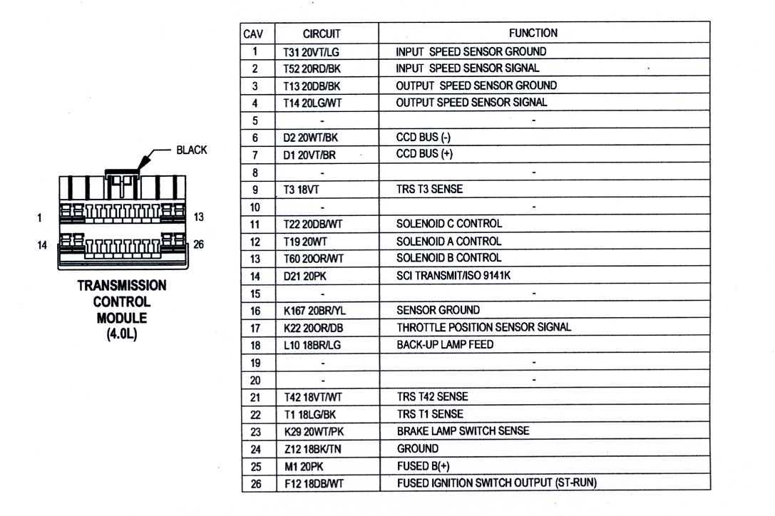
You may want to sneak into the CCD Bus through the TCM connector to see if there's a problem with the wiring going to, or at, the DLC.
Refer to pics.
Diconnect the TCM. Key to RUN.
Check voltage at pin cav 7 and at pin cav 8. You can use pin cav 24 for the meter ground. This is ground G101 on the engine. If the voltage readings are no good, try a ground in the footwell nearby (like the gas pedal pivot bracket mount studs).
If the voltage readings are good (2.5 ish), the DLC or its wiring may be bad.
Do this and tell me want you get.
03-28-2014, 11:53 AM
#12
CF Veteran
Join Date: Aug 2010
Location: Canton, MI
Posts: 8,357
Likes: 0
Received 90 Likes
on
74 Posts
Year: 1999
Model: Cherokee
Engine: 4.0
Here's some data you can read about the CCD Bus Bias and Termination. Note the resistance readings of the CCD Bus for one termination resistor vs. that of two termination resistors wired in parallel (your findings in post #6 above).
Bus Bias and Termination
The voltage network used by the CCD data bus to transmit messages requires both bias and termination. At least one electronic control module on the data bus must provide a voltage source for the CCD data bus network known as bus bias, and there must be at least one bus termination point for the data bus circuit to be complete. However, while bias and termination are both required for data bus operation, they both do not have to be within the same electronic control module. The CCD data bus is biased to approximately 2.5 volts. With each of the electronic control modules wired in parallel to the data bus, all modules utilize the same bus bias. Therefore, based upon vehicle options, the data bus can accommodate two or twenty electronic control modules without affecting bus voltage.
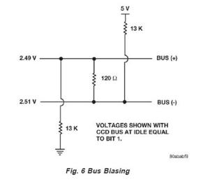
The power supplied to the data bus is known as bus biasing. Bus bias is provided through a series circuit. To properly bias the data bus circuits, a 5 volt supply is provided by the Jeep Cherokee Instrument Cluster through a 13 kilo-ohm resistor to the Bus (�) circuit (Fig. 6).
Voltage from the Bus (�) circuit flows through a 120 ohm termination resistor to the Bus (+) circuit. The Bus (+) circuit is grounded through another 13 kilo-ohm resistor. While at least one termination resistor is required for the system to operate, the Jeep Cherokee system uses two (Instrument Cluster and the PCM). The second termination resistor serves as a backup. These resistors serve as termination points. The two termination resistors, are wired in parallel to each other, giving the CCD bus about 60 ohms total resistance.
The termination resistor provides a path for the bus bias voltage. Without a termination point, voltage biasing would not occur. Voltage would go to 5 volts on one bus wire and 0 volts on the other bus wire. The voltage drop through the termination resistor creates 2.51 volts on Bus (�), and 2.49 volts on Bus (+). The voltage difference between the two circuits is 0.02 volts. When the data bus voltage differential is a steady 0.02 volts, the CCD system is considered �idle.� When no input is received from any module and the ignition switch is in the Off position for a pre-programmed length of time, the bus data becomes inactive or enters the �sleep mode.�
Electronic control modules that provide bus bias can be programmed to �wake up� the data bus and become active upon receiving any predetermined input or when the ignition switch is turned to the On position.
During operational data transfer on the Bus, the voltages on each of the individual CCD bus wires will vary from their 2.5V, with the CCD- being pulled "low" and the CCD+ being pulled "high." The normal idle voltage that resides on CCD+ and CCD� are important specs from a diagnostics point of view. If the voltages are too far off, say above 2.8V or below 1.8V, then the communication on the bus stops completely or becomes invalid.
Bus Failure
The CCD data bus can be monitored using the DRBIII scan tool. However, it is possible for the data bus to pass all tests since the voltage parameters will be in �range� and false signals are being sent. There are essentially 12 �hard failures� that can occur with the CCD data bus:
� Bus Shorted to Battery
� Bus Shorted to 5 Volts
� Bus Shorted to Ground
� Bus (+) Shorted to Bus (�)
� Bus (�) and Bus (+) Open
� Bus (+) Open
� Bus (�) Open
� No Bus Bias
� Bus Bias Level Too High
� Bus Bias Level Too Low
� No Bus Termination
� Not Receiving Bus Messages Correctly
Refer to the appropriate diagnostic procedures for details on how to diagnose these faults using a DRBIII scan tool.
Bus Failure Visual Symptoms & Diagnosis
The following visible symptoms, alone or in combination, may indicate a CCD data bus failure:
� Airbag Indicator Lamp and Malfunction Indicator Lamp (MIL) Illuminated
� Instrument Cluster Gauges (All) Inoperative
� No Compass Mini-Trip Computer (CMTC) Operation
The typical way to diagnose CCD bus faults is to check the voltages on the CCD+ and CCD- wires individually, using pins 3 and 11 of the DLC connector, and measuring each separately to ground. Then, if the bus voltages are incorrect, begin unplugging various modules one at a time until the bus voltages come back to normal range restoring normal communication.
The tricky part of this technique is that if you unplug the Instrument Cluster you have removed the bus bias module during your diagnostics, causing the entire bus goes down
[The 1999 Body Diagnostics Procedures manual states that the Instrument Cluster supplies both bias and termination and the PCM provides a second termination (applies to �97 > Cherokees)]
Bus Bias and Termination
The voltage network used by the CCD data bus to transmit messages requires both bias and termination. At least one electronic control module on the data bus must provide a voltage source for the CCD data bus network known as bus bias, and there must be at least one bus termination point for the data bus circuit to be complete. However, while bias and termination are both required for data bus operation, they both do not have to be within the same electronic control module. The CCD data bus is biased to approximately 2.5 volts. With each of the electronic control modules wired in parallel to the data bus, all modules utilize the same bus bias. Therefore, based upon vehicle options, the data bus can accommodate two or twenty electronic control modules without affecting bus voltage.
The power supplied to the data bus is known as bus biasing. Bus bias is provided through a series circuit. To properly bias the data bus circuits, a 5 volt supply is provided by the Jeep Cherokee Instrument Cluster through a 13 kilo-ohm resistor to the Bus (�) circuit (Fig. 6).
Voltage from the Bus (�) circuit flows through a 120 ohm termination resistor to the Bus (+) circuit. The Bus (+) circuit is grounded through another 13 kilo-ohm resistor. While at least one termination resistor is required for the system to operate, the Jeep Cherokee system uses two (Instrument Cluster and the PCM). The second termination resistor serves as a backup. These resistors serve as termination points. The two termination resistors, are wired in parallel to each other, giving the CCD bus about 60 ohms total resistance.
The termination resistor provides a path for the bus bias voltage. Without a termination point, voltage biasing would not occur. Voltage would go to 5 volts on one bus wire and 0 volts on the other bus wire. The voltage drop through the termination resistor creates 2.51 volts on Bus (�), and 2.49 volts on Bus (+). The voltage difference between the two circuits is 0.02 volts. When the data bus voltage differential is a steady 0.02 volts, the CCD system is considered �idle.� When no input is received from any module and the ignition switch is in the Off position for a pre-programmed length of time, the bus data becomes inactive or enters the �sleep mode.�
Electronic control modules that provide bus bias can be programmed to �wake up� the data bus and become active upon receiving any predetermined input or when the ignition switch is turned to the On position.
During operational data transfer on the Bus, the voltages on each of the individual CCD bus wires will vary from their 2.5V, with the CCD- being pulled "low" and the CCD+ being pulled "high." The normal idle voltage that resides on CCD+ and CCD� are important specs from a diagnostics point of view. If the voltages are too far off, say above 2.8V or below 1.8V, then the communication on the bus stops completely or becomes invalid.
Bus Failure
The CCD data bus can be monitored using the DRBIII scan tool. However, it is possible for the data bus to pass all tests since the voltage parameters will be in �range� and false signals are being sent. There are essentially 12 �hard failures� that can occur with the CCD data bus:
� Bus Shorted to Battery
� Bus Shorted to 5 Volts
� Bus Shorted to Ground
� Bus (+) Shorted to Bus (�)
� Bus (�) and Bus (+) Open
� Bus (+) Open
� Bus (�) Open
� No Bus Bias
� Bus Bias Level Too High
� Bus Bias Level Too Low
� No Bus Termination
� Not Receiving Bus Messages Correctly
Refer to the appropriate diagnostic procedures for details on how to diagnose these faults using a DRBIII scan tool.
Bus Failure Visual Symptoms & Diagnosis
The following visible symptoms, alone or in combination, may indicate a CCD data bus failure:
� Airbag Indicator Lamp and Malfunction Indicator Lamp (MIL) Illuminated
� Instrument Cluster Gauges (All) Inoperative
� No Compass Mini-Trip Computer (CMTC) Operation
The typical way to diagnose CCD bus faults is to check the voltages on the CCD+ and CCD- wires individually, using pins 3 and 11 of the DLC connector, and measuring each separately to ground. Then, if the bus voltages are incorrect, begin unplugging various modules one at a time until the bus voltages come back to normal range restoring normal communication.
The tricky part of this technique is that if you unplug the Instrument Cluster you have removed the bus bias module during your diagnostics, causing the entire bus goes down
[The 1999 Body Diagnostics Procedures manual states that the Instrument Cluster supplies both bias and termination and the PCM provides a second termination (applies to �97 > Cherokees)]
04-02-2014, 08:38 PM
#13
Newbie
Thread Starter
Join Date: Feb 2014
Location: HSV, AL
Posts: 28
Likes: 0
Received 0 Likes
on
0 Posts
Year: 1998
Model: Cherokee
Engine: 4.0
You may want to sneak into the CCD Bus through the TCM connector to see if there's a problem with the wiring going to, or at, the DLC.
Refer to pics.
Diconnect the TCM. Key to RUN.
Check voltage at pin cav 7 and at pin cav 8. [I assume you meant 6 and 7]
You can use pin cav 24 for the meter ground. This is ground G101 on the engine. If the voltage readings are no good, try a ground in the footwell nearby (like the gas pedal pivot bracket mount studs).
If the voltage readings are good (2.5 ish), the DLC or its wiring may be bad.
Do this and tell me want you get.
04-02-2014, 08:47 PM
#14
Newbie
Thread Starter
Join Date: Feb 2014
Location: HSV, AL
Posts: 28
Likes: 0
Received 0 Likes
on
0 Posts
Year: 1998
Model: Cherokee
Engine: 4.0
Here's some data you can read about the CCD Bus Bias and Termination. Note the resistance readings of the CCD Bus for one termination resistor vs. that of two termination resistors wired in parallel (your findings in post #6 above).
The typical way to diagnose CCD bus faults is to check the voltages on the CCD+ and CCD- wires individually, using pins 3 and 11 of the DLC connector, and measuring each separately to ground. Then, if the bus voltages are incorrect, begin unplugging various modules one at a time until the bus voltages come back to normal range restoring normal communication. [/FONT]
The tricky part of this technique is that if you unplug the Instrument Cluster you have removed the bus bias module during your diagnostics, causing the entire bus goes down
[The 1999 Body Diagnostics Procedures manual states that the Instrument Cluster supplies both bias and termination and the PCM provides a second termination (applies to ’97 > Cherokees)]
04-03-2014, 05:44 PM
#15
Newbie

Join Date: Dec 2010
Location: Michigan
Posts: 6
Likes: 0
Received 0 Likes
on
0 Posts
Year: 2000
Model: Cherokee
Engine: 4.oh
Alright, I am having the very same issues yet all my voltages are in range and my ohms appear normal, I think. Quick question. If during the gauge self diagnostic, all the lights work but no analog gauges move, could it still be BUS issues or just a cluster problem. Thanks all for any help.