
98 xj cluster and radio not working
 03-28-2014, 06:49 AM
#16
CF Veteran
Join Date: Aug 2010
Location: Canton, MI
Posts: 8,357
Likes: 0
Received 90 Likes
on
74 Posts
Year: 1999
Model: Cherokee
Engine: 4.0
If so, you are seeing 2 Ohms resistance in both G108 ground circuits. Not full continuity but should be okay. If you are seeing 12 volts at pins 8 and 9 of C1 then the cluster is getting power and ground. At this point I would say that the Instrument Cluster microprocessor is defective and the resolution would be to change the Instrument Cluster.
Did you check the ground for the radio chassis yet?
 03-28-2014, 01:17 PM
#17
Junior Member
Thread Starter

Join Date: Aug 2011
Location: New jersey
Posts: 69
Likes: 0
Received 0 Likes
on
0 Posts
Year: 1998
Model: Cherokee
Engine: 4.0
Did you download '98 FSM from Pacific Coast Manuals like I mentioned in post #12 and determine that the cluster connector pinouts are just like the '97 pinouts, above.
If so, you are seeing 2 Ohms resistance in both G108 ground circuits. Not full continuity but should be okay. If you are seeing 12 volts at pins 8 and 9 of C1 then the cluster is getting power and ground. At this point I would say that the Instrument Cluster microprocessor is defective and the resolution would be to change the Instrument Cluster.
Did you check the ground for the radio chassis yet?
04-04-2014, 03:26 PM
#18
Junior Member
Thread Starter
Join Date: Aug 2011
Location: New jersey
Posts: 69
Likes: 0
Received 0 Likes
on
0 Posts
Year: 1998
Model: Cherokee
Engine: 4.0
So my problem still exists, the previous owner wired in a push button start, it may be a bad ignition switch I'm not sure, I also hear a noise coming from the head light switch here and there, also my horn lmao well that the door button the lets you know it's open well... For sole odd reason that button when I press it in it stops my horn from beeping, the horn button on the steering wheel doesn't control the horn anymore, a couple times my horn would just randomly go off I I pulled the plugs and today I plugged them bak in and opened the door and the horn went off.. I have no clue hopefully some one knows what to do..
04-04-2014, 04:06 PM
#19
CF Veteran
Join Date: Aug 2010
Location: Canton, MI
Posts: 8,357
Likes: 0
Received 90 Likes
on
74 Posts
Year: 1999
Model: Cherokee
Engine: 4.0
So my problem still exists, the previous owner wired in a push button start, it may be a bad ignition switch I'm not sure, I also hear a noise coming from the head light switch here and there, also my horn lmao well that the door button the lets you know it's open well... For sole odd reason that button when I press it in it stops my horn from beeping, the horn button on the steering wheel doesn't control the horn anymore, a couple times my horn would just randomly go off I I pulled the plugs and today I plugged them bak in and opened the door and the horn went off.. I have no clue hopefully some one knows what to do..
04-04-2014, 06:10 PM
#20
Junior Member
Thread Starter
Join Date: Aug 2011
Location: New jersey
Posts: 69
Likes: 0
Received 0 Likes
on
0 Posts
Year: 1998
Model: Cherokee
Engine: 4.0
Haha ok, I am going to look at it this weekend, I'll let you know what I find, thanks man.
04-05-2014, 01:01 PM
#22
CF Veteran
Join Date: Aug 2010
Location: Canton, MI
Posts: 8,357
Likes: 0
Received 90 Likes
on
74 Posts
Year: 1999
Model: Cherokee
Engine: 4.0
Bubba no doubt tapped into the ignition switch wiring so look for butt splices in the wiring coming off the ignition switch. The butt spliced wiring probably went to that push button switch.
04-05-2014, 02:34 PM
#23
Junior Member
Thread Starter
Join Date: Aug 2011
Location: New jersey
Posts: 69
Likes: 0
Received 0 Likes
on
0 Posts
Year: 1998
Model: Cherokee
Engine: 4.0
He tapped into the blue wire and a yellow wire, and ran that to the push button I undid them and connected them back together and heat shrinked it, now when I go to start the jeep nothing happens I hear a relay click in the kicker panel and that's it, no cranking or anything, gauges on cluster still do not work.
04-05-2014, 02:36 PM
#24
Junior Member
Thread Starter
Join Date: Aug 2011
Location: New jersey
Posts: 69
Likes: 0
Received 0 Likes
on
0 Posts
Year: 1998
Model: Cherokee
Engine: 4.0
Also there is a relay below the headlight switch and with the IOD fuse the relay was spazzing out, and was constantly clicking I pull the IOD fuse and it stops, pulled the relay and blinkers stopped working so I put the relay back in and left the IOD fuse out
04-05-2014, 03:47 PM
#25
CF Veteran
Join Date: Aug 2010
Location: Canton, MI
Posts: 8,357
Likes: 0
Received 90 Likes
on
74 Posts
Year: 1999
Model: Cherokee
Engine: 4.0
He tapped into the blue wire and a yellow wire, and ran that to the push button I undid them and connected them back together and heat shrinked it, now when I go to start the jeep nothing happens I hear a relay click in the kicker panel and that's it, no cranking or anything, gauges on cluster still do not work.
The Yellow wiire is the Start circuit wire from the ignition switch to fuse #19 in the Junction Block. from fuse #19 it goes to the Starter Motor Relay in the PDC.
If you didn't connect two Yellow wires (previously cut) together but connected the Yellow wire to the Blue wire, that would be a mistake. The Blue wire was probably added by the PO. You have to find the Yellow wire coming off the ignition Switch, then find the other Yellow wire that would have gone to connector C201 (very large connector under the dash, to the right of the gas pedal) and connect the two.
04-05-2014, 05:43 PM
#26
Junior Member
Thread Starter
Join Date: Aug 2011
Location: New jersey
Posts: 69
Likes: 0
Received 0 Likes
on
0 Posts
Year: 1998
Model: Cherokee
Engine: 4.0
Did you connect the Yellow wire to the Blue wire?
The Yellow wiire is the Start circuit wire from the ignition switch to fuse #19 in the Junction Block. from fuse #19 it goes to the Starter Motor Relay in the PDC.
If you didn't connect two Yellow wires (previously cut) together but connected the Yellow wire to the Blue wire, that would be a mistake. The Blue wire was probably added by the PO. You have to find the Yellow wire coming off the ignition Switch, then find the other Yellow wire that would have gone to connector C201 (very large connector under the dash, to the right of the gas pedal) and connect the two.
04-06-2014, 08:09 AM
#28
CF Veteran
Join Date: Aug 2010
Location: Canton, MI
Posts: 8,357
Likes: 0
Received 90 Likes
on
74 Posts
Year: 1999
Model: Cherokee
Engine: 4.0
Thanks for the pic.
I'm trying to figure out what kind of splicing you did on those wires. THey're not butt spliced, that's for sure, and it doesn't look like they're soldered either.
It's mperative that you have good splices. Soldering is the best but if you can't do that, the next best thing is to use butt splices. You'll need a good pair of wire crimpers/stripers and the proper butt splices. The Blue wire is 12 gauge and the Yellow wire is 14 Gauge. You'll need Yellow butt splices, which will handle both wire sizes, to do the job.
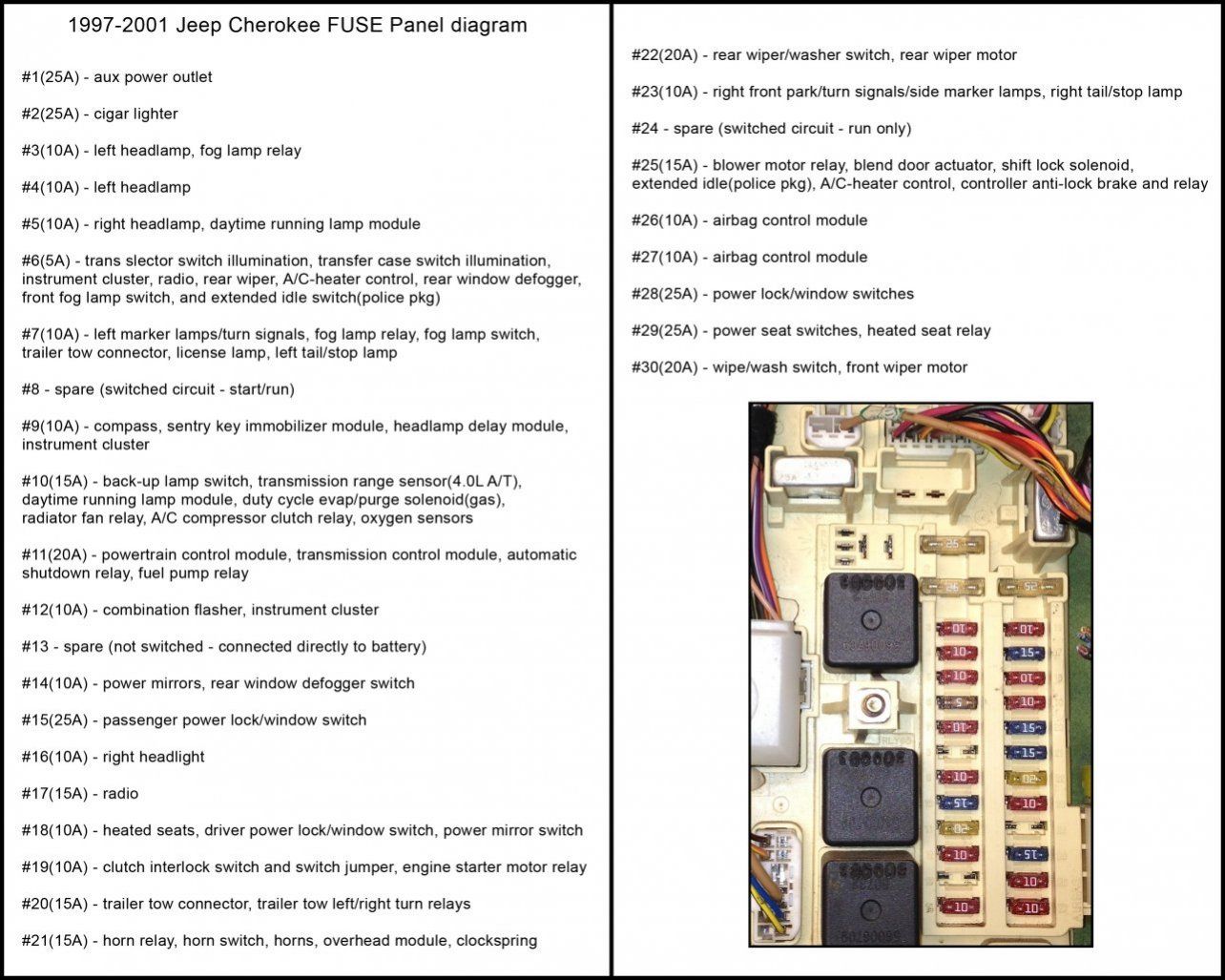
As stated earlier, the Yellow wire is the starter motor circuit. Now, the Blue wire is probably the one that is involved in most of your problems. It's in the Start-Run circuit. Meaning, when you place the ignition switch to RUN or Start, power is transferred through the ignition switch to four (4) fuses in the Junction Block; F9, F10, F11, and F27.
If you get the wires properly spliced and your problems persist I would say that the ignition switch is defective - at least the contacts in the switch for the Blue wire circuit are bad.
To change the ignition switch simply follow the instructions in the FSM that you downloaded from Pacific Coast Manuals.
#1: Butt splice the wires. Do a pull test on the butt spliced wires to see if they are secure in the butt splices.
#2: Test the ignition switch and systems functions.
#3: Replace the ignition switch if required.
#5: Take pics.
Edit: Here's a JB guide that shows the circuits associated with fuses 9, 10, 11, and 27:

I'm trying to figure out what kind of splicing you did on those wires. THey're not butt spliced, that's for sure, and it doesn't look like they're soldered either.
It's mperative that you have good splices. Soldering is the best but if you can't do that, the next best thing is to use butt splices. You'll need a good pair of wire crimpers/stripers and the proper butt splices. The Blue wire is 12 gauge and the Yellow wire is 14 Gauge. You'll need Yellow butt splices, which will handle both wire sizes, to do the job.
As stated earlier, the Yellow wire is the starter motor circuit. Now, the Blue wire is probably the one that is involved in most of your problems. It's in the Start-Run circuit. Meaning, when you place the ignition switch to RUN or Start, power is transferred through the ignition switch to four (4) fuses in the Junction Block; F9, F10, F11, and F27.
If you get the wires properly spliced and your problems persist I would say that the ignition switch is defective - at least the contacts in the switch for the Blue wire circuit are bad.
To change the ignition switch simply follow the instructions in the FSM that you downloaded from Pacific Coast Manuals.
#1: Butt splice the wires. Do a pull test on the butt spliced wires to see if they are secure in the butt splices.
#2: Test the ignition switch and systems functions.
#3: Replace the ignition switch if required.
#5: Take pics.
Edit: Here's a JB guide that shows the circuits associated with fuses 9, 10, 11, and 27:
Last edited by CCKen; 04-06-2014 at 11:07 AM.
04-06-2014, 03:14 PM
#30
Junior Member
Thread Starter
Join Date: Aug 2011
Location: New jersey
Posts: 69
Likes: 0
Received 0 Likes
on
0 Posts
Year: 1998
Model: Cherokee
Engine: 4.0
Thanks for the pic.
I'm trying to figure out what kind of splicing you did on those wires. THey're not butt spliced, that's for sure, and it doesn't look like they're soldered either.
It's mperative that you have good splices. Soldering is the best but if you can't do that, the next best thing is to use butt splices. You'll need a good pair of wire crimpers/stripers and the proper butt splices. The Blue wire is 12 gauge and the Yellow wire is 14 Gauge. You'll need Yellow butt splices, which will handle both wire sizes, to do the job.
As stated earlier, the Yellow wire is the starter motor circuit. Now, the Blue wire is probably the one that is involved in most of your problems. It's in the Start-Run circuit. Meaning, when you place the ignition switch to RUN or Start, power is transferred through the ignition switch to four (4) fuses in the Junction Block; F9, F10, F11, and F27.
If you get the wires properly spliced and your problems persist I would say that the ignition switch is defective - at least the contacts in the switch for the Blue wire circuit are bad.
To change the ignition switch simply follow the instructions in the FSM that you downloaded from Pacific Coast Manuals.
#1: Butt splice the wires. Do a pull test on the butt spliced wires to see if they are secure in the butt splices.
#2: Test the ignition switch and systems functions.
#3: Replace the ignition switch if required.
#5: Take pics.
Edit: Here's a JB guide that shows the circuits associated with fuses 9, 10, 11, and 27: