When you click on links to various merchants on this site and make a purchase, this can result in this site earning a commission. Affiliate programs and affiliations include, but are not limited to, the eBay Partner Network.
Stock XJ Cherokee Tech. All XJ Non-modified/stock questions go hereXJ (84-01)
All OEM related XJ specific tech. Examples, no start, general maintenance or anything that's stock.
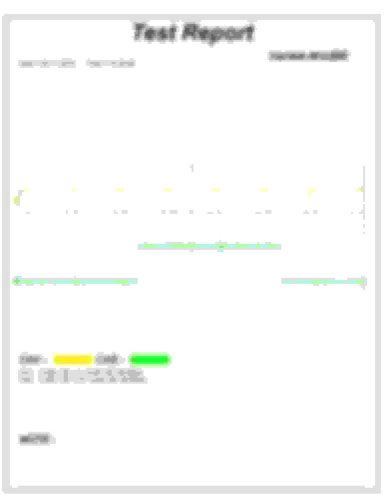
After a very long journey of tracking a code/CEL (p1391) on my jeep I ended up buying an oscilloscope to view my cam position sensor (CMP) and my crankshaft position sensor (CKP) signals. To say the least this was with a massive amount of help on this forum. As a result of the knowledgeable folks on here, it was noticed that my CMP signal had a large spike every time the ignition coil would fire.
This CEL is gone after replacing the CMP, however the signal before and after were as you see below, thus this is unrelated. CH1: PCM ignition coil signal CH2: Cam signal ,Measured at the PCM
It was suggested that I ensure no sensor wires or probe wires were near spark plug wires, which may have attributed to the spike seen in the signal. After a review of the engine bay, I was able to confirm the cam sensor wires were clear of any spark plugs wires and not contacting the ignition coil.
Now the jeep is running fine as it has before learning all of this, so the purpose of this thread is simply to test the waters and see if anyone is interested in seeing what may be causing these spikes. I have no real knowledge on oscilloscopes/wave form analysis so any pursuit here will be fueled by you, ill try my best to accommodate any diagnostic suggestions.
As I had been advised Ive left off on diagnosing from here:
-Thus far I have tried taking these readings from the cam sensor directly, there was no change in the signal.
-I have swept over the ignition coil and coil out wire with a test light, there was no arcing found through this method
-The last suggestion that was given to me was to unbolt the Ignition coil from the block and monitor the signal while moving this unit around a bit, this is currently my next step on trying to learn what is being seen in this signal.
correct me if Im wrong here, but If I understood the suggested reason for this signal spike correctly, the coil may be grounding out every time its firing?
parts for your consideration:
Ignition coil is New Echlin
cap/rotor new Echlin
Spark plug cables Accel 8mm, ohmed before using these months ago
Wiring harness gutted,Reworked/soldered, ohmed ( and this was done for the P1391 witch hunt) though nothing changed from the old harness to this one.
Last edited by 4x4jeepmanthing; 11-29-2019 at 11:31 AM.
not sure I see anything that jumps out as weird to me in that snapshot....but you would need to compare it to others
when a field collapses and a coil and certain sensors are involved, without getting out my textbooks, a spike is usually involved
comments from others of interest
how much did the Hantek cost ?
70-80$ its not monster oscilloscope, but even others with the like have not shown a wave form that has this spike. Don't get me wrong, this scope was not bought to be a very intense capture of waves, just enough to see whats happening.
Would you mind elaborating as to what this collapsed field would entail so far as a jeep goes? If its not scope related, I'm just trying to understand whats being seen, and hopefully providing something to be learned.
thank you
I think you have done very well tracking your issue down...did you say a changed Cam sensor might have been the fix ?
$80 for a scope is about 1hr shop time, and if you want to keep your Jeep on the road forever, will be invaluable, paid for itself with one use anyway
think I may get myself one
Dave may be able to comment on your waveform by comparing it to his, my comment was general relating to Inductive circuit theory, not Jeep ignition in particular
I think it would be more helpful to take screenshots of the Hantek waveform from the computer (Control + PrintScreen) to include the settings. Also pick a color for the coil signal to get better definition (still on holiday and using portable device).
Use measurement function (Measure>Type>Vertical>Maximum).
Reduce the vertical on the coil to be able to see the entire waveform.
Put the -0- of the coil signal on the -0- axis. Move the CPS signal out the way or get rid of it (it may be helpful later to know why some of that extraneous coil activity appears in the CPS while some does not, but it doesn't seem to bother CPS, so it shouldn't bother us).
You're using the attenuator probe for the coil?
Post a picture of your set-up.
Specifically, there looks to be as many as 4 things wrong in each coil waveform, but with that channel's settings at DCx1 (I think it should be 10:1) maybe we're blowing up the Hantek (I mean, there's like negative deflection there).
Anyway, let's get a normal coil waveform going and then try to figure out the spikes.
Year: 1998 Classic (I'll get it running soon....) and 02 Grand
Model: Cherokee (XJ)
Engine: 4.0
Originally Posted by 4x4jeepmanthing
correct me if Im wrong here, but If I understood the suggested reason for this signal spike correctly, the coil may be grounding out every time its firing?
Yes, that's how it fires. The coil is supplied with 12v, and the PCM grounds it to fire it. (Same with the injectors.) That's backwards of most vehicles. Dunno why Jeep did that.
Cool stuff. Thanks for posting this!
Originally Posted by awg
when a field collapses and a coil and certain sensors are involved, without getting out my textbooks, a spike is usually involved
Yep. It's pretty hard to avoid it, and that is an intense field that is collapsing. I would be surprised to NOT see a spike on random wires in the engine compartment. I don't know if that spike we are seeing here is "normal" but I strongly suspect that it is.
Originally Posted by Dave51
I think it would be more helpful to take screenshots of the Hantek waveform from the computer (Control + PrintScreen) to include the settings. Also pick a color for the coil signal to get better definition (still on holiday and using portable device)..
Yep. It's pretty hard to avoid it, and that is an intense field that is collapsing. I would be surprised to NOT see a spike on random wires in the engine compartment. I don't know if that spike we are seeing here is "normal" but I strongly suspect that it is.
I think it would be more helpful to take screenshots of the Hantek waveform from the computer (Control + PrintScreen) to include the settings. Also pick a color for the coil signal to get better definition (still on holiday and using portable device). I remember you mentioning printscreen before, I'm unfamiliar with this option , I'll look into it.
Use measurement function (Measure>Type>Vertical>Maximum). I may need to take a picture of these features, I'm not under the impression they are tunable.
Reduce the vertical on the coil to be able to see the entire waveform.
Put the -0- of the coil signal on the -0- axis. Move the CPS signal out the way or get rid of it (it may be helpful later to know why some of that extraneous coil activity appears in the CPS while some does not, but it doesn't seem to bother CPS, so it shouldn't bother us).
You're using the attenuator probe for the coil? all I have are the two leads that came with the kit.
Post a picture of your set-up. can do once I get it hooked up again. I assume your talking about the on screen set up or probes to?
Specifically, there looks to be as many as 4 things wrong in each coil waveform, but with that channel's settings at DCx1 (I think it should be 10:1) maybe we're blowing up the Hantek (I mean, there's like negative deflection there).
Anyway, let's get a normal coil waveform going and then try to figure out the spikes. As above I'll get some screen shots so you can see what's needing to be adjusted.
When you say DCx1 should the probe be on x1 or x10?
In re: printscreen function, I use Irfanview but there's plenty of free image managers around. Copy the image you want to save using Control + PrntScr then paste it into your image manager. Crop or whatever to clean it up, save it to desktop and then upload it to CF.
In re: attentuation search "attenu" in the manual and read the results as they pop up, especially p. 25. You should be using the attenuation probe for the coil and other high voltage signals, so in your software choose X10 (my software uses 10:1 but it's the same thing)(I think your probe settings are reversed according to your image) to get an accurate measurement (the attenuation probe reduces the signal by a factor of 10). Reduce the Vertical by increasing volts.
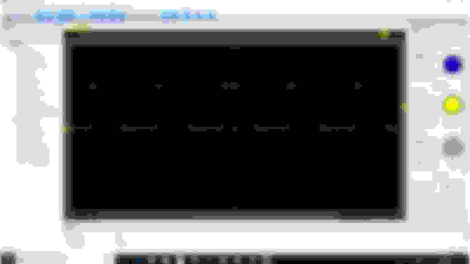
probe on 10x, taken at pcm coil driver out
not really sure how this came out, but I tried adjusting V until it showed enough of the wave not bunched up.
I can't read the set-up or measured values-- are you cheating and using a camera?
Fiddle with the measurement tool some more. It looks like it chops the top off of the waveform in Vertical > Maximum so move it up some more.
Originally Posted by 4x4jeepmanthing;
probe on 10x, taken at pcm coil driver out.
Whoa, look of surprise! I did not see that coming! Huge bounce out of the gate!
BTW I was thinking you were measuring at the coil wire that goes to the distributor, which would seem to have been a more likely candidate for scatter. Better measurement tools for that are the HT-25 Ignition Cable and CC-650 Current Clamp. HT-25 comes with Hantek 1008, CC-650 is extra. Back when we thought it was only a CPK/CPS problem, 6022BE did the job effectively, but you can now we're a little limited if we want start measuring some of the high voltage stuff (you can Rube something up to measure big coil wire voltage by wrapping a wire around it and gator it to the attenuator probe, or just tape the probe in place, Current we got a problem with unless throw some coinage there).
Also, I'm thinking I like 1008 software a little better, Tools seem a little easier to use and it does have the automotive templates, but these aren't deal-breakers, more like a matter of convenience.
I can't read the set-up or measured values-- are you cheating and using a camera?
Fiddle with the measurement tool some more. It looks like it chops the top off of the waveform in Vertical > Maximum so move it up some more.
can do!
No I used the print screen function, posted into paint then to CF.
I'm not sure what you mean by not able to read the set up? are you talking about the measurement window? I think I may have closed that out to fit this on the screen. I can recapture this!
out of curiosity have you tried to save any data and if so what format did it save it in?
Last edited by 4x4jeepmanthing; 12-01-2019 at 11:58 AM.

 11-29-2019 | 11:10 AM