When you click on links to various merchants on this site and make a purchase, this can result in this site earning a commission. Affiliate programs and affiliations include, but are not limited to, the eBay Partner Network.
Stock XJ Cherokee Tech. All XJ Non-modified/stock questions go hereXJ (84-01)
All OEM related XJ specific tech. Examples, no start, general maintenance or anything that's stock.
Whoa, look of surprise! I did not see that coming! Huge bounce out of the gate!
BTW I was thinking you were measuring at the coil wire that goes to the distributor, which would seem to have been a more likely candidate for scatter. Better measurement tools for that are the HT-25 Ignition Cable and CC-650 Current Clamp. HT-25 comes with Hantek 1008, CC-650 is extra. Back when we thought it was only a CPK/CPS problem, 6022BE did the job effectively, but you can now we're a little limited if we want start measuring some of the high voltage stuff (you can Rube something up to measure big coil wire voltage by wrapping a wire around it and gator it to the attenuator probe, or just tape the probe in place, Current we got a problem with unless throw some coinage there).
Originally Posted by Dave51
Or, one of the small wires will be the one from the ECU telling the coil to fire.
-sorry I was going off previous suggestions. Ive got some copper wire I could wind around the coil wire for the probe to attach to?
Also, I'm thinking I like 1008 software a little better, Tools seem a little easier to use and it does have the automotive templates, but these aren't deal-breakers, more like a matter of convenience.
yeah I kinda suspected the cheaper scope would lake some of these things.
Ill see what I can conjure up
Last edited by 4x4jeepmanthing; 12-01-2019 at 11:57 AM.
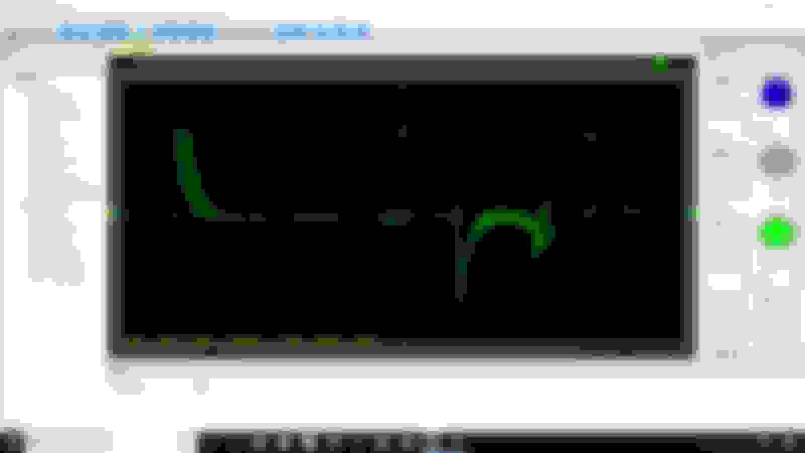
ok probe on x10, Software on x10. hopefully this clears something up lol.
coiled some copper wire around the ignition coil to distributor wire and grounded to the battery.
Now I have some questions, though I think ill wait to ask a couple until I get a better understanding of what we need to set up here. (wave clarity wise)
Once we establish a good wave form let me know please.
I don't suppose my oscilloscope will allow me to trigger off of a Cylinder plug wire? If I'm gaining an understanding of this scope, I'de only be able to monitor one cylinder firing with the secondary ignition wave on another channel, no?
Last edited by 4x4jeepmanthing; 12-01-2019 at 09:19 PM.
Engine: 4.0, new lifters valve job with new springs and exhaust valves, preload set with shims
Is your pcm ground by the coil nice and good?? Thats a weird driver waveform.
I would think shielding the coil wire does nothing to help you. 50k volts is 50k volts, why tempt it to ground out and fry your coil driver.
Now, that waveform for the Cam position sensor looks fine, nice and square. The wave for the coil driver, not so much. Looks a tad noisy. But,
There is no point in looking at it unless you know what it SHOULD look like, I don't offhand. Do you? What voltage?
I would like to know if you have compared the CKPS to the coil secondary output, or even the input, obviously they should all line up on the time base (horizontally) since the CKPS is what triggers the coil to fire.
Is your pcm ground by the coil nice and good?? Thats a weird driver waveform. I would think shielding the coil wire does nothing to help you. 50k volts is 50k volts, why tempt it to ground out and fry your coil driver. I havent suggested doing this have I, Im not following?
Now, that waveform for the Cam position sensor looks fine, nice and square. The wave for the coil driver, not so much. Looks a tad noisy. But,
There is no point in looking at it unless you know what it SHOULD look like, I don't offhand. Do you? What voltage? we are talking pre ignition coil yes ( pcm coil driver)?
I would like to know if you have compared the CKPS to the coil secondary output, or even the input, obviously they should all line up on the time base (horizontally) since the CKPS is what triggers the coil to fire.
I have not tried CKPS and the secondary out together/pcm coil out, the grounds are all very clean and tight.
I certainly do not know what a coil driver should look like exactly, but some of my withheld questions related to this and the spark plug wave of ( Dwell, spark V, Firing V, burn time). I wasn't going to press it until I knew if was even showing a wave properly. However if someone does know.............. please share.
I
I certainly do not know what a coil driver should look like exactly...However if someone does know.............. please share.
I'll measure mine when I return from holiday (at this point in my life I'm a professional holiday-taker)(although right now I'm working on a Honda 2.4 L with a jumped timing chain and -0- compression)(needless to say, Honda 2.4s do not take kindly to jumped timing chains) and although I've got a coil rail I'm pretty sure it should be a B+ square waveform.
I don't suppose my oscilloscope will allow me to trigger off of a Cylinder plug wire? If I'm gaining an understanding of this scope, I'de only be able to monitor one cylinder firing with the secondary ignition wave on another channel, no?
You can do anything you want within the limits of the machine, which is
6022BE has a max input voltage of 35V peak (350V with a 10x divider probe)
so before we smoke that thing let me repeat:
We wanted a machine to measure CPS and CPK signals. This does that perfectly.
Once you start to measure high voltage circuits, you need to know that you're staying within the limits of the machine.
The best answer is get the HT-25, a CC-650 current clamp and the 20:1 attenuator (or at least a 20:1 attenuator)(and if ithey're compatible with 6022 (need BNC connector)).
Change thought process. Rather than thinking it's a CPS problem, consider it a coil problem. If you go back to the first waveforms
you've got coil scatterin the CKS too. If all of the Hantek components are away from the coil (these are inexpensive cables so probably very susceptible to interference) then we should consider the coil leak (short) to ground instead of CPS.
You could try doing additional investigatory experimentation (screwing around) by looking at other sensors (injectors or stuff near the coil) to see if there's artifact there as well.
And IMO, you're seeing that in the coil driver as well.
coiled some copper wire around the ignition coil to distributor wire and grounded to the battery.
Originally Posted by Dave51
Cause why?
Originally Posted by Dave51
Back when we thought it was only a CPK/CPS problem, 6022BE did the job effectively, but you can now we're a little limited if we want start measuring some of the high voltage stuff (you can Rube something up to measure big coil wire voltage by wrapping a wire around it and gator it to the attenuator probe, or just tape the probe in place, Current we got a problem with unless throw some coinage there).
.
Last edited by 4x4jeepmanthing; 12-02-2019 at 08:30 AM.
oiled some copper wire around the ignition coil to distributor wire and grounded to the battery.
implies that the coil is grounded to the battery. Do you mean the attenuator probe is hooked to the coiled wire and the Hantek is grounded to the battery?

 12-01-2019, 11:44 AM