When you click on links to various merchants on this site and make a purchase, this can result in this site earning a commission. Affiliate programs and affiliations include, but are not limited to, the eBay Partner Network.
Got both sides buttoned up, took it for a ride down an old access road with a few whoops. It did awesome. I could hear and feel when they first made their contact, but after that, smooth. Can't say that for the rear though, bottomed those out haha. I have progressive rears waiting to go on though.
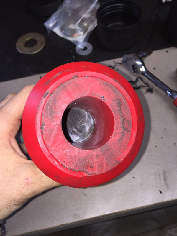
I used a steel spacer to center the bigger washer around the bolt so it wouldn't shift around from repetitive contact. Used locktite on the bolt, and cranked it on the tower:
Sweet!
On another note, is there an issue with the upper control arm busing on axle? The bolt/sleeve should be centered in 'can' of bushing. If off center it is due to a failed bushing, or binding in suspension.
Have you seen the pics of the rear bumps I installed?
Sweet! On another note, is there an issue with the upper control arm busing on axle? The bolt/sleeve should be centered in 'can' of bushing. If off center it is due to a failed bushing, or binding in suspension. Have you seen the pics of the rear bumps I installed?
It's B Lees 3 link, which uses a special press-in JJ for the OEM mount. AFAIK the JJ can handle the movement more than a rubber or poly bushing, but it could also be how the "U" part was welded to the upper link. Or maybe I need to flip the arm 180* now that I think about it. Oh well I'll take a look at it haha.
I haven't seen what you did with rear actually. I have the Prothane rears that are 4", in going to put them on a Dirtbound U-bolt plate, which will end up being the perfect BS spacing I need. Just leave the frame side bare and have it contact the bump on the plate.
I see, being a JJ explains it. Looks like the upper arm has a slight turn to it, that's all. Nothing an adjustment at the other end shouldn't fix. Just to have it centered at ride height.
The only issue I have seen with reversing the rear bumps is, the bump contacts a much smaller area on frame rail, resulting in higher loads and possible creasing/denting of frame rail. In stock configuration, the metal backing plate of bump spreads the load and adds another layer of steel.
Here is how I did it. 'Welded' on additional spring perches to axle. From that, plates or pucks can be added to adjust height (were not needed). Progressive bumps 4.5" are mounted on bump stop brackets from a 90's Nissan pathfinder. Again, it's experimentation to find works, with what I have to work with.
To set them up properly I removed a leaf spring on one side, used the measurement of a fully collapsed shock, and set 'final stop' to be just before full collapse.
I thought about having another perch welded on, but I would have had to make up like 6" of bump, seemed easier to just get the u bolt plate, since I can't weld. I get what your saying about spreading the load though. You think if I had some flat stock welded up there to "reinforce" the area it would be any better?
I see. But do you think it would work with correct bumper like this picture?
Not sure. I need to wait until the plates come in. The studs on my frame broke a year ago when I did the poly ones so I had something welded there already, I'll take a pic tomorrow.
for the rear bump stops you can either buy or make these. No welding needed
I looked into those plates originally. But using 4.5" bumpstops, and with BDS 7 leafs, there was not enough room. And I was working with what I had on hand, avoiding spending coin.
Ok gotcha I was thinking why reinvent something that already exists, but if you had parts hanging around that you could use to fabricate something it would make sense to do so.

 01-29-2016, 12:03 PM